The 7 most common types of concrete damage and how to recognise them early on

Concrete is indispensable in industrial plants - from supporting structures and foundations to chimneys and Silos. However, like all materials, concrete is susceptible to damage that can affect its load-bearing capacity and service life. This article looks at the seven most common types of concrete damage in industrial environments: from mechanical cracking and spalling to chemical influences such as carbonation and chloride attack and biological damage caused by algae growth. Find out how modern Inspection methods help to recognise this damage at an early stage and how preventive measures can reduce maintenance costs and increase safety.

Introduction: Why concrete inspection is essential in industrial plants

Concrete forms the basis of many industrial structures - from supporting pillars to foundations to Storage tanks and silos. In heavy industry and power generation in particular, concrete structures are exposed to high loads and must be inspected regularly in order to detect damage at an early stage. Plant operators can thus increase safety and minimise unplanned downtime.
portrait-karsten
Dipl. Ing. Karsten Lehrke

1. cracking due to mechanical loads

Cracks caused by tensile and shear forces: bending, shear and settlement cracks Mechanical loads are one of the most common causes of cracking in concrete. These cracks - such as bending cracks (perpendicular to the component axis) and shear cracks (at a 45-degree angle) - occur when strength limits are exceeded and are often the first signs of structural weakness. As cracks allow moisture and pollutants to penetrate the structure, the risk of further damage increases. Corrosion.
Basic mechanisms of crack formation
  • Development process
    • Tensile stresses exceed the tensile strength of the concrete.
    • Concrete has only about 10 % of compressive strength as tensile strength.
    • Critical areas are created when these are exceeded.
    • Microcracks develop into macrocracks.
  • Typical load types
    • Direct tension: Perpendicular to the direction of loading, mostly smooth crack surfaces, continuous crack formation.
    • Bending tension: In the drawn cross-sectional area, running from bottom to top, typical for slabs and beams.
    • Shear stresses: Diagonal cracks, 45-degree angle to the component axis, often near the support.
Classification of cracks according to load type
  • Bending cracks
    • Development: By exceeding the bending tensile strength, in the maximum tensile range, perpendicular to the main tensile stress.
    • Characteristics: Start on the tensile side, run perpendicular to the component axis, crack width decreases towards the neutral axis.
    • Typical localisation: lower edge of beams, centre of panels, support areas of continuous structures.
  • Shear cracks
    • Development: By exceeding the shear strength, in areas of high shear force, combination of tensile and shear stresses.
    • Characteristics: Diagonal course, approx. 45° to the component axis, often in conjunction with bending cracks.
    • Critical areas: Areas close to supports, load application points, cross-section cracks.
  • Torsional cracks
    • Caused by torsion of the component, exceeding the torsional strength.
    • Characteristics: Helical crack pattern, circumferential around the component, constant inclination to the component axis.
Assessment of crack widths
  • Permissible crack widths
    • According to exposure class:
      • Interiors: max. 0.3 mm
      • External components: max. 0.2 mm
      • Hydraulic structures: max. 0.1 mm
    • After use:
      • Parking decks: max. 0.3 mm
      • Industrial floors: max. 0.2 mm
      • Watertight components: max. 0.1 mm
  • Crack measurement
    • Measuring methods: Crack width measuring magnifier, crack width ruler, digital crack width measurement, crack propagation measurement.
    • Documentation: crack width, crack length, crack course, crack depth (if possible).
Assessment of the risk of cracking
  • Risk factors
    • Design factors: Component geometry, degree of reinforcement, load application, changes in cross-section.
    • Technical material factors: Concrete quality, reinforcement arrangement, bond behaviour, concrete cover.
  • Damage potential
    • Immediate consequences: Visual impairment, fitness for purpose, durability, load-bearing capacity.
    • Long-term consequences: Corrosion of the reinforcement, frost damage, chemical attack, loss of strength.
Preventive measures
  • Constructive measures
    • Reinforcement optimisation: Sufficient quantity of reinforcement, favourable distribution, correct anchoring, joint design.
    • Component design: avoidance of cross-sectional jumps, load distribution, joint arrangement, deformation possibilities.
  • Concrete technology measures
    • Concrete composition: Suitable strength class, low shrinkage, good workability, high tensile strength.
    • Execution: Careful compaction, adequate post-treatment, temperature management, quality control.
Monitoring and documentation
  • Regular checks
    • Inspection intervals: After initial load, in the event of load changes, periodic inspection, after special events.
    • Documentation: crack detection, photo documentation, development process, action log.
  • Monitoring
    • Measurements: Crack width change, deformations, temperatures, loads.
    • Evaluation: trend analysis, limit value monitoring, root cause analysis, forecasts.

2. chipping on edges and surfaces

Surface damage due to freeze-thaw cycles and mechanical effects Spalling can occur due to mechanical stress or freeze-thaw cycles and expose the underlying reinforcement. Such damage is to be expected, especially in areas with high traffic or strong temperature fluctuations, and should be treated in good time to protect the steel reinforcement from corrosion.
Definition and appearance
  • Edge chipping:
    • Damage to exposed corners and edges
    • Exposed aggregates
    • Sharp or chipped edges
    • Different depths of damage
  • Surface spalling:
    • Extensive detachment of the concrete cover
    • Nesting
    • Exposed reinforcement
    • Different spalling depths
Types of damage
  • Flat flaking:
    • Depth up to 5 mm
    • Mostly close to the surface
    • Often large-scale
    • No reinforcement exposure
  • Medium spalling:
    • Depth 5-20 mm
    • Partially up to the reinforcement
    • Local concentration
    • Possible reinforcement exposure
  • Deep spalling:
    • Depth > 20 mm
    • Right behind the reinforcement
    • Mostly localised damage
    • Always with reinforcement exposure
Causes of spalling
  • Mechanical causes
    • Impacts:
      • Vehicle collision
      • Falling objects
      • Vandalism
      • Construction work
    • Overload:
      • Point load application
      • Exceeding the load-bearing capacity
      • Dynamic loads
      • Vibrations
    • Abrasion:
      • Wear and tear due to traffic
      • Abrasive stress
      • Hydraulic erosion
      • Mechanical cleaning
  • Chemical causes
    • Reinforcement corrosion:
      • Volume increase due to rust
      • Blasting pressure on concrete cover
      • Progressive damage development
      • Often net-like crack formation beforehand
    • Chemical attack:
      • Acid attack
      • Sulphate effect
      • Alkali reactions
      • Chloride effect
  • Physical causes
    • Freeze-thaw cycle:
      • Water absorption
      • Ice lens formation
      • Explosive effect
      • Near-surface destruction
    • Temperature effect:
      • Thermal stresses
      • Different expansions
      • Temperature shock
      • Influence of fire
  • Production-related causes
    • Concrete technology errors:
      • Incorrect concrete composition
      • Unsuitable surcharges
      • Lack of compaction
      • Incorrect post-treatment
    • Execution error:
      • Insufficient concrete cover
      • Incorrect formwork position
      • Faulty reinforcement routing
      • Inadequate compaction
Damage analysis and assessment
  • Research methods
    • Visual inspection:
      • Damage mapping
      • Photo documentation
      • Surveying
      • Crack detection
    • Non-destructive testing:
      • Tapping
      • Ultrasound
      • Radar
      • Thermography
    • Material testing:
      • Drill core extraction
      • Adhesion test
      • Carbonation depth
      • Chloride content
  • Damage assessment
    • Geometric recording:
      • Spalling depth
      • Surface expansion
      • Exposure of reinforcement
      • Cracking
    • Structural significance:
      • Influence on load-bearing capacity
      • Relevance to stability
      • Suitability for use
      • Durability
Repair measures
  • Immediate measures
    • Fuse:
      • Barrier
      • Support
      • Emergency backup
      • Relief
    • Documentation:
      • Damage documentation
      • Photo documentation
      • Surveying
      • Logging
  • Permanent repair
    • Substrate preparation:
      • Recording damaged areas
      • Concrete removal
      • Reinforcement cleaning
      • Corrosion protection
    • Reprofiling:
      • Bonding bridge
      • Reprofiling mortar
      • Surface finish
      • Aftercare
  • Preventive measures
    • Constructive protection:
      • Edge protection profiles
      • Collision protection
      • Deflector
      • Protective layers
    • Surface protection:
      • Impregnation
      • Coating
      • Wear layers
      • Sealings
Quality assurance
  • Execution control
    • Examinations:
      • Material testing
      • Liability check
      • Coating thickness measurement
      • Surface inspection
    • Documentation:
      • Test protocols
      • Material certificates
      • Photo documentation
      • Acceptance protocol
  • Follow-up checks
    • Inspection intervals:
      • Initial inspection after completion
      • Regular checks
      • Special tests
      • Long-term monitoring
    • Maintenance:
      • Cleaning
      • Care
      • Small repairs
      • Documentation
Economic aspects
  • Cost consideration
    • Direct costs:
      • Material costs
      • Labour costs
      • Scaffolding position
      • Construction site equipment
    • Indirect costs:
      • Restriction of use
      • Business interruption
      • Consequential damage
      • Impairment
  • Prevention costs
    • Protective measures:
      • Constructive protection
      • Surface protection
      • Monitoring
      • Maintenance
    • Life cycle:
      • Initial investment
      • Maintenance costs
      • Maintenance costs
      • Renewal costs

3. carbonation: loss of corrosion protection

Chemical reaction caused by CO₂ - threat to the reinforcement Carbonation is a slow process in which CO₂ from the air reacts with the concrete and lowers the pH value. This attacks the protective layer around the steel reinforcement, which can lead to corrosion. A simple phenolphthalein test can be used to visualise carbonation zones.
Basics of carbonation
  • The carbonation process
    • Chemical reaction:
      • CO₂ + H₂O → H₂CO₃ (carbonic acid)
      • H₂CO₃ + Ca(OH)₂ → CaCO₃ + H₂O
      • Conversion of calcium hydroxide into calcium carbonate
      • pH value drops from approx. 13 to below 9
    • Influencing factors:
      • CO₂ concentration in the air
      • Relative humidity (optimum for 50-70%)
      • Temperature
      • Pore structure of the concrete
  • Carbonation front
    • Course:
      • Progressing from the outside in
      • Relatively even front
      • Depth of carbonation increases with √t
      • Slowdown with increasing depth
    • Measurement:
      • Phenolphthalein test
      • Colour change at pH > 8.2
      • Pink: not carbonated
      • Colourless: carbonated
Effects on the reinforcement protection
  • Passivation of the reinforcement
    • In an alkaline environment:
      • pH value > 12.5 in healthy concrete
      • Formation of a passive layer on the steel
      • Protection against corrosion
      • Stable oxide layer
    • Depassivation:
      • Destruction of the protective layer at pH < 9
      • Start of possible corrosion processes
      • Loss of electrochemical protection
      • Increased susceptibility to corrosion
  • Risk of corrosion
    • Requirements for corrosion:
      • Depassivation through carbonation
      • Sufficient humidity
      • Presence of oxygen
      • Electrochemical potential
    • Types of corrosion:
      • Surface corrosion
      • Pitting corrosion
      • Crevice corrosion
      • Stress corrosion cracking
Factors influencing carbonation
  • Concrete composition
    • Cement type:
      • Type of cement
      • Cement content
      • Additives
      • Water-cement ratio
    • Concrete quality:
      • Pore structure
      • Compaction
      • Aftercare
      • Strength
  • Environmental conditions
    • Atmospheric conditions:
      • CO₂ concentration
      • Air humidity
      • Temperature
      • Weather influences
    • Exposure:
      • Indoor/outdoor area
      • Irrigation
      • Cover
      • Microclimate
Measurement and monitoring
  • Research methods
    • Phenolphthalein test:
      • Drill core extraction
      • Fresh fracture surfaces
      • Indicator solution
      • Colour change
    • Alternative methods:
      • Thermogravimetry
      • X-ray diffraction
      • pH measurement
      • Microscopy
  • Forecast models
    • Depth of carbonation:
      • x = k - √t
      • x = carbonation depth
      • k = carbonation coefficient
      • t = time
    • Influencing factors:
      • Environmental conditions
      • Concrete quality
      • Exposure
      • Aftercare
Protective measures
  • Preventive measures
    • Concrete technology measures:
      • Low water-cement ratio
      • Sufficient cement content
      • Suitable cement type
      • Careful compaction
    • Constructive measures:
      • Sufficient concrete cover
      • Water drainage
      • Geometric design
      • Joint seal
  • Surface protection
    • Coating systems:
      • CO₂ brakes
      • Hydrophobisation
      • Sealing
      • Thick coating
    • Application:
      • Substrate preparation
      • System selection
      • Application
      • Quality control
Repair
  • Damage assessment
    • Diagnosis:
      • Carbonation depth
      • Concrete cover
      • Corrosion damage
      • Concrete quality
    • Rating:
      • Extent of damage
      • Development forecast
      • Repair urgency
      • Selection of measures
  • Repair methods
    • Concrete removal:
      • Carbonated concrete
      • Exposing the reinforcement
      • Substrate preparation
      • Cleaning
    • Reprofiling:
      • Corrosion protection
      • Bonding bridge
      • Repair mortar
      • Surface protection
Quality assurance
  • Execution control
    • Examinations:
      • Material properties
      • Layer thicknesses
      • Adhesive strength
      • Surface quality
    • Documentation:
      • Test protocols
      • Material certificates
      • Photo documentation
      • Acceptance protocol
  • Long-term monitoring
    • Monitoring:
      • Regular inspection
      • Carbonation measurement
      • Corrosion monitoring
      • Documentation
    • Maintenance:
      • Cleaning
      • Control
      • Repair
      • Renewal

4. chloride attack and pitting corrosion

Aggressive influences in road salt and coastal environments In multi-storey car parks, bridges or facilities near the coast, chlorides can penetrate the concrete and cause pitting corrosion. This type of corrosion is localised and can weaken structural components abruptly. Regular inspection of such exposed structures is essential.
Basics of the chloride attack
  • Input sources of chlorides
    • External sources:
      • De-icing agents in winter service
      • Sea water and spray
      • Industrial atmosphere
      • Saline soils
    • Internal sources:
      • Contaminated aggregates
      • Chloride-containing additives
      • Mixing water
      • Contaminated material
  • Transport mechanisms
    • Penetration paths:
      • Capillary suction
      • Diffusion
      • Convection
      • Cracks and flaws
    • Influencing factors:
      • Pore structure
      • Moisture content
      • Temperature
      • Concrete quality
Corrosion mechanisms
  • Pitting corrosion
    • Origin:
      • Local destruction of the passive layer
      • Formation of anodes and cathodes
      • Concentration of corrosion
      • Progressive deepening
    • Process:
      • Chlorides penetrate concrete cover
      • Achieve critical concentration
      • Breaking through passive layer
      • Formation of corrosion centres
  • Electrochemical processes
    • Anodic reaction:
      • Fe → Fe²⁺ + 2e- (iron dissolution)
      • Formation of rust products
      • Volume increase
      • Explosive effect
    • Cathodic reaction:
      • ½O₂ + H₂O + 2e- → 2OH-
      • Oxygen reduction
      • pH value change
      • Corrosion acceleration
Damage mechanisms
  • Direct injury
    • Reinforcement corrosion:
      • Cross-section loss
      • Loss of strength
      • Loss of ductility
      • Compound loss
    • Concrete damage:
      • Cracking
      • Spalling
      • Structural loosening
      • Loss of strength
  • Damage patterns
    • External signs:
      • Rust flags
      • Cracks along the reinforcement
      • Spalling
      • Efflorescence
    • Internal damage:
      • Cavities
      • Corrosion products
      • Structural damage
      • Compound faults
Examination and diagnosis
  • Measurement methods
    • Chloride content:
      • Drill meal analysis
      • Titration
      • Ion chromatography
      • Chloride profiles
    • Corrosion investigation:
      • Potential measurement
      • Resistance measurement
      • Polarisation measurement
      • Ultrasound
  • Evaluation criteria
    • Critical chloride levels:
      • Limit values according to standards
      • Chloride/cement ratio
      • Probability of corrosion
      • Exposure classes
    • Degree of damage:
      • Initiation phase
      • Propagation phase
      • Damage phase
      • Failure phase
Preventive measures
  • Constructive measures
    • Concrete cover:
      • Sufficient thickness
      • Quality control
      • Exposure-compliant dimensioning
      • Safety surcharges
    • Component design:
      • Water drainage
      • Avoidance of water retention
      • Accessibility
      • Inspection options
  • Concrete technology measures
    • Concrete composition:
      • Low w/c value
      • High cement content
      • Pozzolanic additives
      • Dense microstructure
    • Special measures:
      • Corrosion-resistant reinforcement
      • Stainless steel reinforcement
      • Coated reinforcement
      • Inhibitors
Repair
  • Maintenance concepts
    • Protection principles:
      • W - Prevent water ingress
      • C - Remove chlorides
      • R - Protect reinforcement
      • K - Cathodic corrosion protection
    • Process selection:
      • Extent of damage
      • Accessibility
      • Economic efficiency
      • Durability
  • Repair methods
    • Conventional methods:
      • Concrete removal
      • Reinforcement cleaning
      • Reprofiling
      • Surface protection
    • Special procedures:
      • Electrochemical chloride extraction
      • Cathodic corrosion protection
      • Recalculation
      • Crack injections
Monitoring and maintenance
  • Monitoring systems
    • Measuring equipment:
      • Chloride sensors
      • Corrosion sensors
      • Moisture measurement
      • Potential measurement
    • Data acquisition:
      • Continuous measurement
      • Limit value monitoring
      • Trend analysis
      • Documentation
  • Maintenance concepts
    • Regular checks:
      • Visual inspections
      • Measurements
      • Sampling
      • Documentation
    • Preventive measures:
      • Cleaning
      • Surface care
      • Repairs
      • Renewal of protective coatings

5. freeze-thaw damage

Repeated freeze-thaw cycles lead to structural loosening In cold climates, water penetrates the pores of the concrete and freezes, damaging the structure and causing spalling. De-icing salts can accelerate this process. Regular inspection is advisable, especially in free-standing structures or unprotected areas of the system.
Basic damage mechanisms
  • Physical processes
    • Water absorption:
      • Capillary suction effect
      • Pore structure of the concrete
      • Degree of saturation
      • Critical water content
    • Ice formation:
      • Volume increase by approx. 9%
      • Ice lens formation
      • Hydraulic pressure
      • Micro ice lenses in pores
  • Damage phases
    • Phase 1: Water penetration
      • Filling the capillary pores
      • Reaching critical saturation
      • Moisture distribution
      • Transport mechanisms
    • Phase 2: Freezing process
      • Ice formation in larger pores
      • Water transport to ice lenses
      • Build-up of blasting pressure
      • Progressive structural damage
Factors influencing frost damage
  • Concrete properties
    • Pore structure:
      • Pore size distribution
      • Pore volume
      • Capillary porosity
      • Air pore system
    • Strength:
      • Compressive strength
      • Tensile strength
      • Microstructure density
      • Bond strength
  • Environmental influences
    • Temperature:
      • Minimum temperature
      • Cooling speed
      • Number of freeze-thaw cycles
      • Duration of frost periods
    • Humidity:
      • Water supply
      • Degree of moisture penetration
      • Drying option
      • Precipitation
Typical damage patterns
  • Surface damage
    • Weathering:
      • Loss of the cement layer
      • Exposing the aggregates
      • Surface roughness
      • Progressive destruction
    • Spalling:
      • Shell-shaped detachments
      • Edge damage
      • Sanding
      • Structural loosening
  • Structural damage
    • Internal structural damage:
      • Microcrack formation
      • Pore wall damage
      • Compound faults
      • Loss of strength
    • Crack formation:
      • Surface cracks
      • Mesh cracks
      • Deep cracks
      • Structural loosening
Reinforcing factors
  • De-icing salt effect
    • Mechanisms:
      • Increased water saturation
      • Osmotic pressure
      • Concentration gradient
      • Salt enrichment
    • Additional loads:
      • Chemical attack
      • Crystallisation pressure
      • Temperature shock
      • Leaching
  • Constructive weak points
    • Geometric factors:
      • Water retention
      • Lack of drainage
      • Exposed edges
      • Material transitions
    • Execution defects:
      • Insufficient compaction
      • Incorrect post-treatment
      • Incorrect concrete cover
      • Poorly formed joints
Examination and diagnosis
  • Test methods
    • Non-destructive testing:
      • Ultrasound
      • Radar
      • Thermography
      • Knock test
    • Laboratory tests:
      • Freeze-thaw test
      • CIF test/CDF test
      • Microscopy
      • Porosity measurement
  • Damage analysis
    • Inventory:
      • Damage mapping
      • Photo documentation
      • Sampling
      • Measurements on site
    • Rating:
      • Extent of damage
      • Loss progression
      • Root cause analysis
      • Need for action
Preventive measures
  • Concrete technology measures
    • Concrete composition:
      • Low w/c value
      • Air-entraining agent
      • Suitable cements
      • Frost-resistant aggregates
    • Processing:
      • Careful compaction
      • Adequate follow-up treatment
      • Protection against early moisture penetration
      • Quality control

6. sulphate attack and internal blasting

Reaction with sulphate-containing water - frequently in Industrial plants and wastewater structures Sulphates from certain industrial wastewater or natural sources can lead to chemical reactions in concrete, known as ettringite formation. This process can crack the concrete structure from the inside and impair its stability. Such damage often occurs in systems that come into contact with sulphate-containing water.
Basics of sulphate attack
  • Sulphate sources
    • External sources:
      • Groundwater
      • Sea water
      • Industrial waste water
      • Soils and rocks
      • Fertiliser
      • Atmospheric influences
    • Internal sources:
      • Gypsum cement
      • Sulphate-containing aggregates
      • Contaminated additives
      • Contaminated mixing water
  • Chemical reactions
    • Primary reactions:
      • Formation of ettringite (3CaO-Al₂O₃-3CaSO₄-32H₂O)
      • Gypsum formation (CaSO₄-2H₂O)
      • Thaumasite formation (CaSiO₃-CaCO₃-CaSO₄-15H₂O)
    • Secondary effects:
      • pH value changes
      • Calcium leaching
      • Structural loosening
      • Loss of strength
Damage mechanisms
  • Ettringite formation
    • development process:
      • Reaction with C₃A
      • Volume increase up to 160%
      • Crystal growth in pores
      • Build-up of blasting pressure
    • Influencing factors:
      • Sulphate concentration
      • Temperature
      • Moisture supply
      • Pore structure
  • Inner blasting

7. biological damage caused by algae and moss

Damp concrete surfaces offer ideal conditions for growth Algae and moss can thrive on damp concrete surfaces and contribute to long-term damage to the surface. In shaded areas or with poor drainage, biological growth can accumulate, increasing the moisture load on the concrete and weakening the surface.
Basics of biological fouling
  • Conditions of origin
    • Environmental factors:
      • Moisture
      • Temperature
      • Incidence of light
      • Nutrient supply
    • Building-related factors:
      • Surface roughness
      • Porosity
      • Water retention capacity
      • pH value of the surface
  • Forms of colonisation
    • algae species:
      • Green algae
      • Blue-green algae
      • Diatoms
      • Red algae
    • Moss species:
      • Cushion mosses
      • Cushion mosses
      • Liverwort
      • Deciduous mosses
Damage mechanisms
  • Physical damage
    • Mechanical effects:
      • Root growth in pores
      • Explosive effect due to volume increase
      • Surface erosion
      • Structural loosening
    • Moisture influences:
      • Increased water absorption
      • Prolonged moisturisation
      • Freeze-thaw cycle
      • Capillary water pipe
  • Chemical damage
    • Metabolic products:
      • Organic acids
      • CO₂ production
      • Humic substances
      • Enzymes
    • Material changes:
      • pH value reduction
      • Carbonation
      • Mineral dissolution
      • Salt formation
Damage patterns
  • Visual impairments
    • Discolouration:
      • Green to black coatings
      • Blotchy appearance
      • Striping
      • Colour changes
    • Surface changes:
      • Gloss changes
      • Soiling
      • Structural changes
      • Patina
  • Substantial damage
    • Surface damage:
      • Roughening
      • Sanding
      • Weathering
      • Structural loosening
    • Consequential damage:
      • Increased moisture load
      • Freeze-thaw damage
      • Accelerated carbonation
      • Corrosion promotion
Risk factors and exposure
  • Structural factors
    • Constructive aspects:
      • Lack of overlap
      • Inadequate drainage
      • Horizontal surfaces
      • Missing drip edges
    • Surface properties:
      • Roughness
      • Porosity
      • Water absorption
      • Alkalinity
  • Ambient conditions
    • Climatic factors:
      • Precipitation frequency
      • Air humidity
      • Shading
      • Temperature conditions
    • Location factors:
      • Vegetation in the neighbourhood
      • Degree of air pollution
      • Exposure to the main weather direction
      • Altitude
Examination and diagnosis
  • On-site investigations
    • Visual inspection:
      • Vegetation mapping
      • Photo documentation
      • Damage pattern
      • Moisture measurement
    • Sampling:
      • Surface swabs
      • Material samples
      • Fouling samples
      • pH value measurement
  • Laboratory tests
    • Biological analysis:
      • Species identification
      • Growth analysis
      • Vitality determination
      • Population density
    • Material analysis:
      • Surface structure
      • Porosity
      • Moisture content
      • Salt content
Preventive measures
  • Constructive measures
    • Water drainage:
      • Slope arrangement
      • Drip edges
      • Covers
      • Drainage
    • Surface design:
      • Smooth surfaces
      • Water-repellent materials
      • Optimised joint design
      • Ventilation options
  • Material-specific measures
    • Surface modification:
      • Hydrophobisation
      • Biocidal additives
      • pH value stabilisation
      • Pore closure
    • Coating systems:
      • Algicidal coatings
      • Self-cleaning surfaces
      • UV-resistant systems
      • Breathable coatings
Cleaning and refurbishment
  • Cleaning methods
    • Mechanical processes:
      • High pressure cleaning
      • Brushing process
      • Blasting
      • Scraping
    • Chemical processes:
      • Biocide treatment
      • pH value regulation
      • Oxidative processes
      • Surfactant treatment
  • Aftercare
    • Protective measures:
      • Hydrophobisation
      • Coating
      • Impregnation
      • Sealing
    • Preventive treatment:
      • Long-term protection
      • Maintenance concept
      • Inspection intervals
      • Documentation
Maintenance and servicing
  • Maintenance concept
    • Regular measures:
      • Inspection
      • Cleaning
      • Checking the protective layers
      • Repairs
    • Documentation:
      • Maintenance log
      • Photo documentation
      • Recording of measures
      • Performance review
  • Long-term strategy
    • Monitoring:
      • Regular checks
      • Fouling development
      • Damage progress
      • Effectiveness of the measures
    • Optimisation:
      • Adaptation of the measures
      • Improving prevention
      • Cost optimisation
      • Sustainability aspects

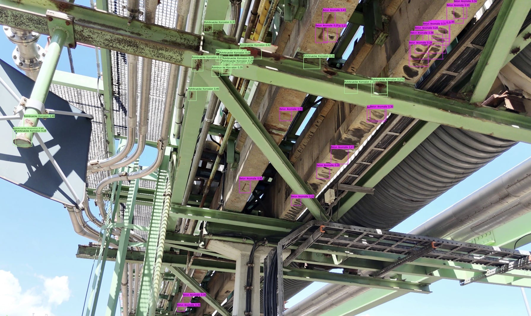
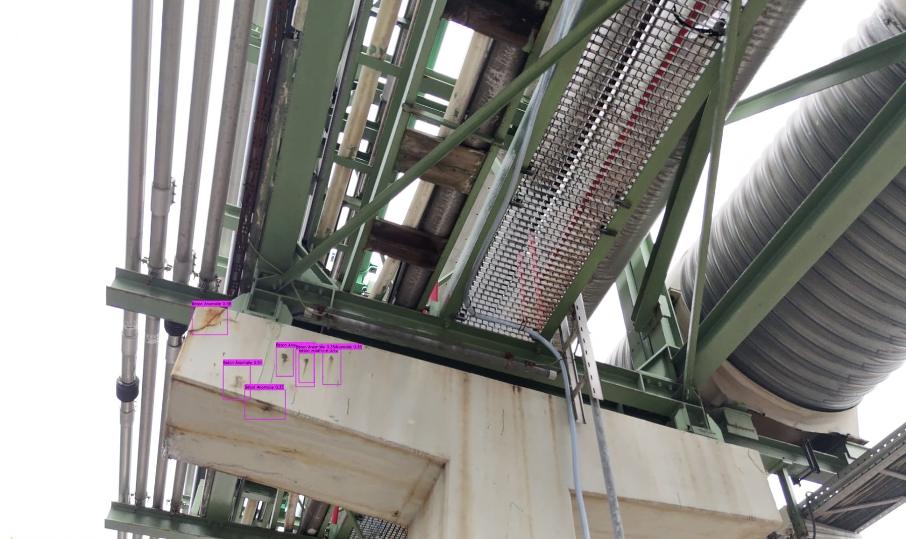
Modern inspection methods: Drones and sensor technology

Efficient inspection of hard-to-reach areas
Nowadays, modern inspection methods such as drones and sensors make it much easier to monitor concrete structures. Drones with high-resolution cameras, Kameras, Thermography and LiDAR can provide detailed images and models of areas that are difficult to access. This data can be used to systematically map and analyse damage. Ultrasonic sensors also make it possible to measure the thickness of the concrete in order to detect cavities or weak points at an early stage.

Preventive maintenance: a must for system operators

Cost reduction through regular inspections and preventive measures Regular inspections and a preventive maintenance strategy are a worthwhile investment for operators. Recognising damage at an early stage and rectifying it in a targeted manner can prevent costly and time-consuming repairs and extend the service life of structures. A preventive maintenance strategy not only minimises costs, but also increases operational safety and avoids unplanned downtime.

Conclusion

Concrete is a robust building material, but it is susceptible to certain types of damage that can affect its service life and load-bearing capacity. With modern inspection techniques and a well thought-out maintenance strategy, plant operators can minimise the risk of damage and ensure the long-term safety of their structures. Regular inspections are the key to optimising maintenance and increasing efficiency in the industry.

Ensure the longevity of your concrete structures - let us work together to recognise and rectify damage at an early stage!

  • We look forward to your enquiry and will respond promptly!

Your data will be processed in accordance with our Privacy policy processed.

Frequently asked questions

Drones make it possible to quickly survey concrete surfaces that are difficult to access, such as elevated bridge areas or concrete façades. This allows inspections to be carried out more quickly, reducing downtime and labour costs.
Drones eliminate the need for inspectors to climb onto scaffolding or into dangerous areas such as high silos or narrow shafts. This improves safety by minimising risks for inspectors.
Modern drones are equipped with high-resolution cameras and special sensors that precisely document tiny cracks, spalling and surface damage on concrete surfaces and record them for analysis.
Underwater drones are ideal for concrete structures that are partially or completely under water such as bridge piers, harbour walls and dams. They enable inspection in difficult water areas without the need for time-consuming preparations such as lowering divers.
Drones capture detailed data that makes signs of damage such as cracks, corrosion and carbonisation visible. This allows damage to be recognised at an early stage and targeted measures to be taken before these problems become cost-intensive.
Using high-resolution photos and 3D models, drones can precisely depict surface conditions and structural deficiencies in concrete structures, making it easier to assess weak points such as cracks or changes in volume.
The data captured by drones can be used to create documentation, damage mapping and historical comparisons. This allows the progress of damage to be tracked and assessed over time.
Yes, drones can capture large areas such as tunnels and multi-storey car parks in a very short time and provide precise data for damage analysis and maintenance planning. This saves an enormous amount of time compared to manual inspections.
Drones with thermographic or LiDAR sensors can visualise temperature fluctuations and cracks caused by freeze-thaw cycles. This allows damage to be recognised at an early stage before it worsens.
By eliminating the need for expensive preparations such as scaffolding and cranes Drone inspections costs considerably. They can also be carried out more quickly, which also reduces indirect costs that could arise due to downtime.
en_GBEnglish